A circuit breaker panel is the heart of a home or workplace electrical system, ensuring safe and efficient power distribution. Understanding its wiring diagram is crucial for proper installation, troubleshooting, and maintaining electrical safety and efficiency.
What is a Circuit Breaker Panel?
A circuit breaker panel, also known as a breaker box or load center, is a critical component of an electrical system. It serves as the central distribution point for power in a building, connecting the main electrical supply to individual circuits. The panel contains circuit breakers, bus bars, and neutral and grounding systems. Its primary function is to protect circuits from overloads and short circuits by tripping breakers when issues arise. Understanding the wiring diagram of a circuit breaker panel is essential for safe installation, troubleshooting, and ensuring compliance with electrical codes.
Importance of a Wiring Diagram for Installation and Troubleshooting
A wiring diagram is essential for installing and troubleshooting a circuit breaker panel. It provides a clear visual representation of the electrical system, showing how components like breakers, bus bars, and wires are connected. This guide ensures proper installation, preventing errors that could lead to safety hazards or system malfunctions. During troubleshooting, the diagram helps identify issues quickly, such as overloaded circuits or faulty connections, saving time and reducing risks; It also ensures compliance with electrical codes and safety standards, making it a critical tool for both professionals and DIYers working on electrical systems.
Key Components of a Circuit Breaker Panel
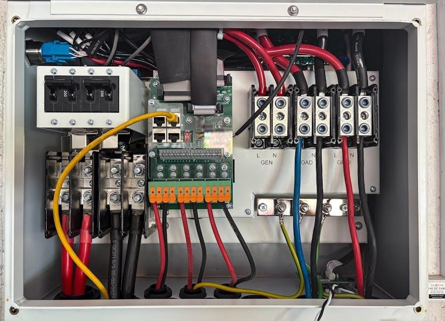
A circuit breaker panel consists of essential components like the main breaker, branch breakers, bus bars, neutral bus bar, and grounding system, ensuring safe and efficient power distribution.
Main Circuit Breaker
The main circuit breaker is the primary component that controls the electrical supply to the entire panel. It acts as the central shut-off point for the whole electrical system, ensuring safety during overloads or short circuits. Typically located at the top or side of the panel, it has a higher ampere rating than branch breakers, matching the total capacity of the electrical service. Proper installation of the main breaker is crucial to prevent power surges and ensure efficient energy distribution. Understanding its role is essential for safe troubleshooting and maintenance of the electrical system.
Branch Circuit Breakers
Branch circuit breakers are responsible for controlling individual electrical circuits within a building. Each breaker corresponds to a specific circuit, such as lighting, outlets, or appliances, ensuring safe power distribution. Proper sizing based on the load is essential to prevent overloading. When a circuit becomes overloaded or experiences a short, the breaker trips, protecting the system from damage. Installation involves connecting the hot wire to the breaker and securing it to the panel. Understanding their role in a wiring diagram helps in organizing and maintaining electrical systems efficiently, ensuring safety and compliance with electrical codes.
Bus Bars
Bus bars are conductive metal strips within a circuit breaker panel that distribute electrical power to various components. They connect the main circuit breaker to branch breakers and ensure consistent power flow. The main bus bar carries live power from the main breaker, while neutral and grounding bus bars handle return paths and safety connections. Proper connection of wires to bus bars is critical for safe and efficient power distribution. They are clearly labeled in wiring diagrams, making it easier to trace circuits and perform troubleshooting. Bus bars play a vital role in maintaining the integrity and functionality of the entire electrical system.
Neutral Bus Bar
The neutral bus bar is a critical component in a circuit breaker panel, serving as the common connection point for all neutral wires in the system. It is connected to the main neutral service wire coming into the panel and provides a return path for current to flow back to the power source. The neutral bus bar is typically bonded to the grounding system to ensure electrical safety and proper fault protection. In wiring diagrams, it is clearly labeled, allowing for easy identification and troubleshooting of neutral circuit connections. Proper installation and connection of the neutral bus bar are essential for reliable and safe electrical system operation.
Grounding System
The grounding system in a circuit breaker panel ensures electrical safety by providing a safe path for fault currents to the earth. It consists of a grounding bus bar connected to the main grounding wire and a grounding rod buried outside the building. This system protects against electrical shocks and equipment damage by safely dissipating fault currents. A proper grounding system is essential for the operation of GFCI and AFCI breakers, which rely on it to function correctly. Wiring diagrams clearly illustrate the grounding connections, emphasizing their importance in maintaining a safe and reliable electrical system.
Understanding the Wiring Diagram
Understanding the wiring diagram is crucial for safe installation and troubleshooting. It provides a clear visual representation of the electrical system, aiding in identifying components and their connections.
Reading Symbols and Labels
Reading symbols and labels in a circuit breaker panel wiring diagram is essential for understanding the electrical system. Common symbols include circles representing circuit breakers, lines signifying wires, and grounding symbols. Labels identify components like “hot,” “neutral,” and “ground” wires, ensuring safe connections. Understanding these elements helps in identifying circuit pathways, troubleshooting issues, and ensuring compliance with safety standards. Accurate interpretation prevents electrical hazards and ensures efficient system operation.
Interpreting Circuit Connections
Interpreting circuit connections in a wiring diagram involves understanding how components like breakers, bus bars, and wires are linked. Hot wires connect to breakers, while neutral and ground wires attach to respective bars. Labels and symbols guide the flow of electricity, ensuring safe connections. This interpretation is crucial for installing circuits correctly, troubleshooting issues, and maintaining electrical safety. By analyzing these connections, you can identify overloaded circuits, improper wiring, or potential hazards, ensuring your system operates efficiently and safely. Clear understanding of these connections is vital for DIY installations or professional electrical work.
Step-by-Step Wiring Process
The step-by-step wiring process begins with preparing the panel, planning the circuit layout, and ensuring all connections are safe and meet electrical codes. Organize wires neatly and verify each connection for power distribution efficiency.
Preparing the Panel for Wiring
Preparing the panel involves de-energizing it by switching off the main breaker and verifying no power is present using a voltage tester. Mount the panel securely, ensuring it’s level and accessible. Remove the cover and organize wires neatly, securing them with cable clamps to prevent damage. Identify and label each circuit based on the wiring diagram to avoid confusion. Ensure all components, such as bus bars and grounding systems, are clean and free from debris. Double-check that the panel is properly grounded and meets local electrical codes before proceeding with connections. Proper preparation ensures a safe and efficient wiring process.
Connecting Neutral and Ground Wires
Connect the neutral wire to the neutral bus bar in the panel, ensuring it is securely fastened. For AFCI or GFCI breakers, attach the neutral wire directly to the designated screw terminal on the breaker. The grounding wire should be connected to the grounding bus bar, which is typically bonded to the panel’s enclosure. Verify that all connections are tight and meet local electrical codes. Properly connecting neutral and ground wires ensures safe operation, prevents electrical shocks, and maintains the integrity of the circuit. Always refer to the wiring diagram for specific configurations and connections.
Installing Branch Circuits
Begin by identifying the branch circuit requirements, ensuring each breaker matches the load’s amperage rating (e.g., 15A, 20A). Connect the hot wire to the appropriate branch breaker, securing it firmly. For AFCI or GFCI breakers, attach the neutral wire directly to the breaker’s terminal. The neutral wire for standard breakers connects to the neutral bus bar. Grounding wires are connected to the grounding bus bar, ensuring electrical safety. Always follow the wiring diagram to avoid overloading circuits. Double-check connections for tightness and compliance with local codes to ensure safe and efficient operation of the electrical system.
Connecting Hot Wires to Breakers
Connect the hot wires to the branch circuit breakers by matching the wire gauge to the breaker’s amp rating. Ensure the wire is securely attached to the breaker’s terminal. For standard breakers, the hot wire connects to the breaker’s terminal, while AFCI or GFCI breakers may require additional neutral wire connections. After connecting, turn the breaker to the “on” position and verify power using a voltage tester. Always de-energize the panel before starting work and wear protective gear to avoid electrical hazards. Proper connections ensure safe and reliable power distribution throughout the electrical system.
Safety Tips and Precautions
Always de-energize the panel before work and use a voltage tester to confirm power is off. Wear protective gear, including gloves and safety goggles, to prevent injuries. Adhere to local electrical codes and ensure all connections are secure to avoid hazards. Proper safety measures are essential for preventing electrical shocks, arcs, and fires during installation or troubleshooting.
De-Energizing the Panel Before Work
Before starting any work on a circuit breaker panel, always switch off the main breaker to de-energize the system. Use a voltage tester to confirm no power is present, ensuring your safety. Secure the panel with a lockout/tagout device to prevent accidental re-energization. This step is critical to avoid electrical shocks or arcs during installation or troubleshooting. Never rely on visual inspections alone; always verify with a tester; Proper de-energization ensures a safe working environment, protecting you from potential electrical hazards. This precaution is non-negotiable for any electrical work.
Using Proper Protective Gear
When working with a circuit breaker panel, wearing proper protective gear is essential to prevent electrical shocks and injuries. Always wear insulated gloves rated for high voltage, safety glasses, and an arc-rated jacket or clothing. A voltage tester should be used to ensure the panel is de-energized before starting work. Additionally, use non-conductive tools and ensure your work area is clear of flammable materials. Secure loose clothing and avoid jewelry that could conduct electricity. Proper protective gear minimizes risks and ensures a safe working environment. Neglecting this step can lead to severe injuries or fatalities.
Adhering to Local Electrical Codes
Adhering to local electrical codes is critical when working with circuit breaker panels to ensure compliance with safety and legal standards. These codes dictate wiring practices, breaker sizes, and panel configurations to prevent hazards. Always consult your area’s specific regulations before starting any installation or modification. Hiring a licensed electrician is recommended to guarantee adherence to these codes. Failure to comply can result in fines, fire risks, or system rejection during inspections. Proper permitting and inspections are essential to validate the work. Following local codes ensures a safe and reliable electrical system that meets legal requirements and protects against potential dangers.
Troubleshooting Common Issues
Troubleshooting circuit breaker panels involves identifying overloaded circuits, diagnosing tripped breakers, and ensuring proper wiring connections. Use wiring diagrams to trace and resolve issues efficiently.
Identifying Overloaded Circuits
An overloaded circuit occurs when excessive current flows through a branch circuit, often causing breakers to trip. Signs include frequent tripping, warm outlets, or unusual odors. To identify overloaded circuits, review the wiring diagram to check connections and load distribution. Ensure no high-power devices are connected to low-rated circuits. Verify that circuit breakers match the load requirements, as specified in the wiring diagram. Overloaded circuits can lead to electrical hazards, so addressing them promptly is crucial for safety. Consult the wiring diagram or a professional if issues persist.
Diagnosing Tripped Breakers
Tripped breakers indicate potential electrical issues, such as overloads or short circuits. To diagnose, start by identifying the affected circuit using the wiring diagram. Unplug devices on the circuit to isolate the problem. Check for short circuits by testing wires with a multimeter. If a GFCI breaker trips, ensure no ground faults exist in the circuit. Verify that the breaker is rated for the connected load. Consult the wiring diagram to trace connections and ensure proper installation. Resetting the breaker after addressing the issue may resolve the problem, but persistent tripping requires professional inspection to prevent hazards.
Understanding and working with circuit breaker panels requires careful planning and adherence to safety guidelines. A wiring diagram is essential for efficient installation and troubleshooting, ensuring all components are correctly connected. By following the steps outlined and using proper techniques, you can maintain a safe and reliable electrical system. Always prioritize safety, use appropriate tools, and consult professionals if unsure. Familiarizing yourself with the panel’s layout and connections will empower you to handle electrical tasks confidently, ensuring your home or workplace remains powered securely and efficiently.